
Interpolated Control (VIC) Port Reference Guide

BT.656 Video Capture Mode
Video Capture Port3-6 SPRU629
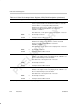
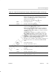
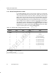
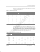
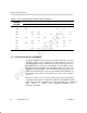
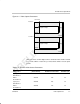
Table 3–4. Error Correction by Protection Bits (Continued)
Received
P
3
–P
0
Bits
Received F, V, and H Bits
Received
P
3
–P
0
Bits
111110101100011010001000
0111 100 – – 011 100 100 100 –
1000 000 ––––101 110 –
1001 – 001 010 ––––111
1010 – 101 010 – 101 101 – 101
1011 010 – 010 010 – 101 010 –
1100 – 001 110 – 110 – 110 110
1101 001 001 – 001 – 001 110 –
1110 –––011 – 101 110 –
1111
– 001 010 – 100 – – –
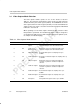
3.2.3 BT.656 Image Window and Capture
The BT.656 format is an interlaced format consisting of two fields. The video
port allows capture of one or both fields. The captured image is a subset of
each field and can be larger or smaller than the active video region. The cap-
tured image position is defined by the VCxSTRT1 and VCxSTOP1 registers
for field 1, and the VCxSTRT2 and VCxSTOP2 registers for field 2. The
VCXSTART and VCXSTOP bits set the horizontal window position for the field
relative to the HCOUNT pixel counter. The VCYSTART and VCYSTOP bits set
the vertical position relative to the VCOUNT line counter. This is shown in
Figure 3–1.
HCOUNT increments on every chroma sample period (every other VCLKIN
rising edge) for which capture is enabled. Once VCOUNT = VCYSTART, line capture
begins when HCOUNT = VCXSTART. It continues until HCOUNT = VCXSTOP. A
field’s capture is complete when HCOUNT = VCXSTOP and
VCOUNT = VCYSTOP.