
Interpolated Control (VIC) Port Reference Guide

BT.656 Video Capture Mode
3-5Video Capture PortSPRU629
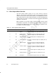
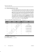
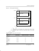
Bits P0, P1, P2, and P3 have different states depending on the state of bits F,
V, and H as shown in Table 3–3.
Table 3–3. BT.656 Protection Bits
Line Information Bits Protection Bits
F V H P3 P2 P1 P0
0 0 0 0 0 0 0
001 1101
010 1011
011 0110
100 0111
101 1010
110 1100
1
1 1 0 0 0 1
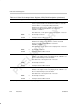
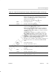
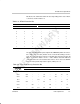
The protection bits allow the port to implement a DEDSEC (double error detec-
tion, single error correction) function on the received video timing reference
code. The corrected values for the F, H, and V bits based on the protection bit
values are shown in Table 3–4. The – entries indicate detected double bit
errors that cannot be corrected. Detection of these errors causes the SERRx
bit in the video port interrupt status register (VPIS) to be set.
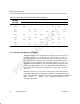
Table 3–4. Error Correction by Protection Bits
Received
Received F, V, and H Bits
R
ece
i
ve
d
P
3
–P
0
Bits
000
001 010 011 100 101 110 111
0000 000 000 000 – 000 – – 111
0001 000 ––111 – 111 111 111
0010 000 ––011 – 101 ––
0011 ––010 – 100 ––111
0100 000 ––011 ––110 –
0101 – 001 ––100 ––111
0110
– 011 011 011 100 – – 011