
Interpolated Control (VIC) Port Reference Guide

BT.656 Video Capture Mode
Video Capture Port3-4 SPRU629
3.2.2 BT.656 Timing Reference Codes
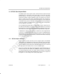
For standard digital video, there are two reference signals, one at the begin-
ning of each video data block (start of active video, SAV), and one at the end
of each video block (end of active video, EAV). (Technically each line begins
with the SAV code and ends just before the subsequent EAV code.) Each
timing reference signal consists of a four sample sequence in the following for-
mat: FF.Ch 00.0h 00.0h XY.0h. (The FFh and 00h values are reserved for use
in these timing reference signals.) The first three bytes are a fixed preamble.
The fourth byte contains information defining field identification, the state of
field blanking and state of line blanking. The assignment of these bits within
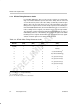
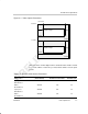
the timing reference signal is listed in Table 3–2. Note that the two least-signifi-
cant bits should be ignored even during 10-bit operation.
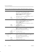
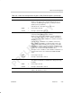
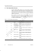
Table 3–2. BT.656 Video Timing Reference Codes
Data Bit
1
st
Byte
(FFh)
2
nd
Byte
(00h)
3
rd
Byte
(00h)
4
th
Byte
(XYh)
9 (MSB) 1 0 0 1
8100 F (field)
†
7100 V (vertical blanking)
‡
6100H (horizontal blanking)
§
5100 P3 (protection bit 3)
¶
4100 P2 (protection bit 2)
¶
3100 P1 (protection bit 1)
¶
2100 P0 (protection bit 0)
¶
1xxx x
0
x x x x
†
F = 0 during Field 1; F = 1 during Field 2
‡
V = 0 elsewhere; V = 1 during field blanking
§
H = 0 in SAV; H = 1 in EAV
¶
P0, P1, P2, and P3: Depends on F, V, and H state.