
Interpolated Control (VIC) Port Reference Guide

Video Port Control Registers
Video Port2-24 SPRU629
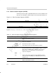
2.7.4 Video Port Interrupt Status Register (VPIS)
The video port interrupt status register (VPIS) displays the status of video port
interrupts to the DSP. The interrupt is only sent to the DSP if the corresponding
enable bit in VPIE is set. All VPIS bits are cleared by writing a 1, writing a 0 has
no effect. The VPIS is shown in Figure 2–6 and described in Table 2–9.
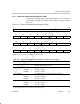
Figure 2–6. Video Port Interrupt Status Register (VPIS)
31 24
Reserved
R-0
23 22 21 20 19 18 17 16
LFDB
SFDB VINTB2 VINTB1 SERRB CCMPB COVRB GPIO
R/WC-0 R/WC-0 R/WC-0 R/WC-0 R/WC-0 R/WC-0 R/WC-0 R/WC-0
15 14 13 12 11 10 9 8
Reserved
DCNA DCMP DUND TICK STC Reserved
R-0 R/WC-0 R/WC-0 R/WC-0 R/WC-0 R/WC-0 R-0
76543210
LFDA
SFDA VINTA2 VINTA1 SERRA CCMPA COVRA Reserved
R/WC-0 R/WC-0 R/WC-0 R/WC-0 R/WC-0 R/WC-0 R/WC-0 R-0
Legend: R = Read only; WC = Write 1 to clear, write of 0 has no effect; -n = value after reset
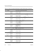
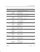
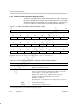
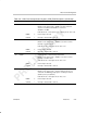
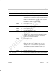
Table 2–9. Video Port Interrupt Status Register (VPIS) Field Descriptions
Bit field symval Value Description
31–24 Reserved – 0 Reserved. The reserved bit location is always read as 0. A value
written to this field has no effect.
23 LFDB Long field detected on channel B interrupt detected bit. (A long
field is only detected when the VRST bit in VCBCTL is cleared to
0; when VRST = 1, a long field is always detected.)
BT.656 or Y/C capture mode – LFDB is set when long field
detection is enabled and VCOUNT is not reset before
VCOUNT = YSTOP + 1.
Raw data mode, or TSI capture mode or display mode – Not used.
NONE 0 No interrupt is detected.
CLEAR 1 Interrupt is detected. Bit is cleared.
†
For CSL implementation, use the notation VP_VPIS_field_symval