
Interpolated Control (VIC) Port Reference Guide

Operational Details
VCXO Interpolated Control Port6-4 SPRU629
Any time a packet with a PCR is received, the timestamp for that packet is
compared with the PCR value in software. A PLL is implemented in software
to synchronize the STCLK with the system time clock. The DSP updates the
VIC input register (VICIN) using the output from this algorithm, which in turn
drives the VCTL output that controls the system time clock VCXO.
If f is the frequency of PCRs in the incoming bit stream, the interpolation rate
R of the VCTL output is given in Equation 6–1, where k is determined by the
precision β specified by you.
Equation 6–1. Relationship Between Interpolation Rate and Input Frequency
R + kf
Equation 6–2 gives the relation between k and the precision β.
Equation 6–2. Relationship of Frequency Multiplier to Precision
k u (
3
Ǹ
(p
2
(2
b
* 1)
2
)ń3)
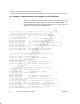
Table 6–2 gives some k and R values for different β’s with f fixed at 40 kHz.
Once a suitable interpolation frequency is determined, the clock divider can
be set.
Table 6–2. Example Values for Interpolation Rate
β k R
9 96.0 3.8 MHz
10 151.0 6.0 MHz
11 240.0 9.6 MHz
12 381.0 15.2 MHz
13 605.0 24.2 MHz
14 960.0 38.4 MHz
15 1523.0 60.9 MHz
16
2418.0 96.7 MHz