
Interpolated Control (VIC) Port Reference Guide

Video Port FIFO
1-7OverviewSPRU629
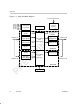
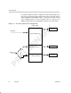
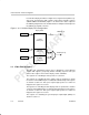
For 8/10-bit raw video, the FIFO is split into channel A and B, as shown in
Figure 1–3. Each FIFO is clocked independently with the channel A FIFO
receiving data from the VDIN[9–0] half of the bus and the channel B FIFO
receiving data from the VDIN[19–10] half of the bus. Each channel’s FIFO has
a separate write pointer and read register (YSRCx). The FIFO configuration
is identical for TSI capture, but channel B is disabled.
Figure 1–3. 8/10-Bit Raw Video Capture and TSI Video Capture FIFO Configuration
VDIN[19–10]
8/10
Buffer B (2560 bytes)
Capture FIFO B
YSRCB
64
VDIN[9–0]
8/10
Buffer A (2560 bytes)
Capture FIFO A
YSRCA
64