
Interpolated Control (VIC) Port Reference Guide


Video Display Registers
4-85Video Display PortSPRU629
4.12.23 Video Display Clipping Register (VDCLIP)
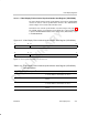
The video display clipping register (VDCLIP) is shown in Figure 4–61 and
described in Table 4–28.
The video display module in the BT.656 and Y/C modes performs program-
mable clipping. The clipping is performed as the last step of the video pipeline.
It is applied only on the image areas defined by VDIMGSZn and VDIMGOFFn
inside the active video area (blanking values are not clipped).
VDCLIP allows output values to be clamped within the specified values. The
default values are the BT.601-specified peak black level of 16 and peak white
level of 235 for luma and the maximum quantization levels of 16 and 240 for
chroma. For 10-bit operation, the clipping is applied to the 8 MSBs of the value
with the 2 LSBs cleared. (For example, a Y value of FF.8h is clipped to EB.0h
and a Y value of 0F.4h is clipped to 10.0h.)
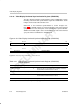
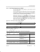
Figure 4–61. Video Display Clipping Register (VDCLIP)
31 24 23 16
CLIPCHIGH
CLIPCLOW
R/W-1111 0000 R/W-0001 0000
15 8 7 0
CLIPYHIGH
CLIPYLOW
R/W-1110 1011 R/W-0001 0000
Legend: R/W = Read/Write; -n = value after reset
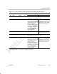
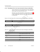
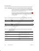
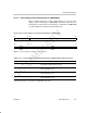
Table 4–28. Video Display Clipping Register (VDCLIP) Field Descriptions
Description
Bit field
†
symval
†
Value
BT.656 and Y/C Mode
Raw Data Mode
31–24 CLIPCHIGH OF(value) 0–FFh A Cb or Cr value greater than
CLIPCHIGH is forced to the
CLIPCHIGH value.
Not used.
23–16 CLIPCLOW OF(value) 0–FFh A Cb or Cr value less than
CLIPCLOW is forced to the
CLIPCLOW value.
Not used.
15–8 CLIPYHIGH OF(value) 0–FFh A Y value greater than CLIPYHIGH is
forced to the CLIPYHIGH value.
Not used.
7–0 CLIPYLOW OF(value) 0–FFh A Y value less than CLIPYLOW is
forced to the CLIPYLOW value.
Not used.
†
For CSL implementation, use the notation VP_VDCLIP_field_symval