
Interpolated Control (VIC) Port Reference Guide


Video Display Registers
4-79Video Display PortSPRU629
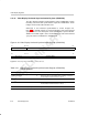
4.12.17 Video Display Field 1 Vertical Synchronization Start Register (VDVSYNS1)
The video display field 1 vertical synchronization start register (VDVSYNS1)
controls the start of vertical synchronization in field 1. The VDVSYNS1 is
shown in Figure 4–55 and described in Table 4–22.
Generation of the vertical synchronization is shown in Figure 4–6, page 4-7.
The VSYNC signal is asserted whenever the frame line counter (FLCOUNT)
is equal to VSYNCYSTART1 and the frame pixel counter (FPCOUNT) is equal
to VSYNCXSTART1.
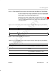
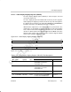
Figure 4–55. Video Display Field 1 Vertical Synchronization Start Register (VDVSYNS1)
31 28 27 16
Reserved
VSYNCYSTART1
R-0 R/W-0
15 12 11 0
Reserved
VSYNCXSTART1
R-0 R/W-0
Legend: R = Read only; R/W = Read/Write; -n = value after reset
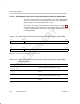
Table 4–22. Video Display Field 1 Vertical Synchronization Start Register (VDVSYNS1)
Field Descriptions
Bit field
†
symval
†
Value Description
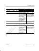
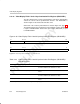
31–28 Reserved – 0 Reserved. The reserved bit location is always read as
0. A value written to this field has no effect.
27–16 VSYNCYSTART1 OF(value) 0–FFFh Specifies the line where VSYNC is asserted for
field 1.
15–12 Reserved – 0 Reserved. The reserved bit location is always read as
0. A value written to this field has no effect.
11–0 VSYNCXSTART1 OF(value) 0–FFFh Specifies the pixel where VSYNC is asserted in
field 1.
†
For CSL implementation, use the notation VP_VDVSYNS1_field_symval