
Interpolated Control (VIC) Port Reference Guide

Display Timing Examples
Video Display Port4-38 SPRU629
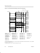
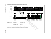
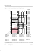
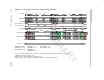
Figure 4–34. BT.656 Interlaced Display Vertical Timing Example
5
FLCOUNT
525
240
240
ILCOUNT
Field 1 Blanking
Field 2 Blanking
Field 1 Active
Field 2 Active
4
3
2
1
240
240
240
240
19
20
21
240
240
240
263
264
265
266
267
282
283
284
524
525
1
240
240
240
240
240
240
240
240
240
240
240
22
23
285
286
Field 1 Image
Field 2 Image
262
1
2
240
239
240
1
2
239
VF
11
10
11
11
01
01
01
00
00
00
01
01
11
11
11
10
10
10
11
11
240
EAV
00
00
00
00
00
10
10
10
00
6 240 01
268 240 11
269 240 11
Active
Horizontal
Output
Blanking Value
Blanking Value
Blanking Value
Blanking Value
Blanking Value
Blanking Value
Blanking Value
Blanking Value
Default Value§
Default Value§
Default Value§
FIFO Data
FIFO Data
FIFO Data
FIFO Data
Default Value§
Blanking Value
Blanking Value
Blanking Value
Blanking Value
Blanking Value
Blanking Value
Blanking Value
Default Value§
Default Value§
Default Value§
FIFO Data
FIFO Data
FIFO Data
Blanking Value
FIFO Data
Blanking Value
VBLNK
†
§
VSYNC
†
§
FLD
IMGVOFF1 = 3 VBLNKXSTART1 = 720 VSYNCXSTART1 = 720 FLD1XSTART = 720
IMGVSIZE1 = 240 VBLNKYSTART1 = 1 VSYNCYSTART1 = 4 FLD1YSTART = 1
IMGVOFF2 = 3 VBLNKXSTOP1 = 720 VSYNCXSTOP1 = 720 FLD2XSTART = 360
IMGVSIZE2 = 240 VBLNKYSTOP1 = 20 VSYNCYSTOP1 = 7 FLD2YSTART = 263
FRMHEIGHT = 525 VBLNKXSTART2 = 360 VSYNCXSTART2 = 360
VBITSET1 = 1 VBLNKYSTART2 = 263 VSYNCYSTART2 = 266 FBITSET = 266
VBITCLR1 = 20 VBLNKXSTOP2 = 360 VSYNCXSTOP2 = 360 FBITCLR = 4
VBITSET2 = 264 VBLNKYSTOP2 = 283 VSYNCYSTOP2 = 269
VBITCLR2 = 283
†
Assumes VCT2P bit in VPCTL is set to 1 (active-low output). VSYNC output when VCTL2S bit in VDCTL is set to 00, VBLNK
output when VCTL2S bit is set 01.
§
If DVEN bit in VDCTL is set to 1; otherwise, blanking value is output