
Interpolated Control (VIC) Port Reference Guide


Video Capture Registers
Video Capture Port3-64 SPRU629
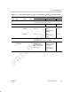
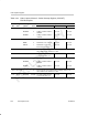
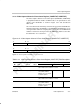
Table 3–20. Video Capture Channel x Vertical Interrupt Register (VCxVINT)
Field Descriptions
Description
Bit field
†
symval
†
Value BT.656 or Y/C Mode Raw Data Mode TSI Mode
31 VIF2 Setting of VINT in field 2 enable bit.
DISABLE 0 Setting of VINT in field 2 is
disabled.
Not used. Not used.
ENABLE 1 Setting of VINT in field 2 is
enabled.
Not used. Not used.
30 FSCL2 FSYNC bit cleared in field 2 enable bit.
NONE 0 FSYNC bit is not cleared. Not used. Not used.
FIELD2 1 FSYNC bit is cleared in
field 2 instead of field 1.
Not used. Not used.
29–28 Reserved – 0 Reserved. The reserved bit location is always read as 0. A
value written to this field has no effect.
27–16 VINT2 OF(value) 0–FFFh Line that vertical interrupt
occurs if VIF2 bit is set.
Not used. Not used.
15 VIF1 Setting of VINT in field 1 enable bit.
DISABLE 0 Setting of VINT in field 1 is
disabled.
Not used. Not used.
ENABLE 1 Setting of VINT in field 1 is
enabled.
Not used. Not used.
14–12 Reserved – 0 Reserved. The reserved bit location is always read as 0. A
value written to this field has no effect.
11–0 VINT1 OF(value) 0–FFFh Line that vertical interrupt
occurs if VIF1 bit is set.
Not used. Not used.
†
For CSL implementation, use the notation VP_VCxVINT_field_symval