
Interpolated Control (VIC) Port Reference Guide


Video Capture Registers
3-63Video Capture PortSPRU629
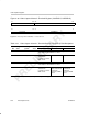
3.13.7 Video Capture Channel x Vertical Interrupt Register (VCAVINT, VCBVINT)
The video capture channel x vertical interrupt register (VCAVINT, VCBVINT)
controls the generation of vertical interrupts in each field. VCxVINT is shown
in Figure 3–35 and described in Table 3–20.
In BT.656 or Y/C mode, an interrupt can be generated upon completion of the
specified line in a field (end of line when VCOUNT = VINTn). This allows the
software to synchronize to the frame or field. The interrupt can be programmed
to occur in one or both fields (or not at all) using the VIF1 and VIF2 bits. The
VINTn bits also determine when the FSYNC bit in VCxSTAT is cleared. If
FSCL2 is 0, then the FSYNC bit is cleared in field 1 when VCOUNT = VINT1;
if FSCL2 is 1, then the FSYNC bit is cleared in field 2 when VCOUNT = VINT2.
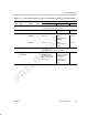
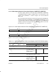
Figure 3–35. Video Capture Channel x Vertical Interrupt Register (VCAVINT, VCBVINT)
31 30 29 28 27 16
VIF2
FSCL2 Reserved VINT2
R/W-0 R/W-0 R-0 R/W-0
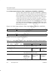
15 14 12 11 0
VIF1 Reserved VINT1
R/W-0 R-0 R/W-0
Legend: R = Read only; R/W = Read/Write; -n = value after reset