
Interpolated Control (VIC) Port Reference Guide


Video Capture Registers
Video Capture Port3-62 SPRU629
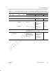
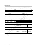
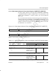
3.13.6 Video Capture Channel x Field 2 Stop Register (VCASTOP2, VCBSTOP2)
The video capture channel x field 2 stop register (VCASTOP2, VCBSTOP2)
defines the end of the field 2-captured image. VCxSTOP2 is shown in
Figure 3–34 and described in Table 3–19.
These registers are not used in raw data mode or TSI mode because their
capture sizes are completely defined by the field 1 start and stop registers.
Figure 3–34. Video Capture Channel x Field 2 Stop Register (VCASTOP2, VCBSTOP2)
31 28 27 16
Reserved
VCYSTOP
R-0 R/W-0
15 12 11 0
Reserved VCXSTOP
R-0 R/W-0
Legend: R = Read only; R/W = Read/Write; -n = value after reset
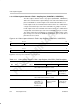
Table 3–19. Video Capture Channel x Field 2 Stop Register (VCxSTOP2) Field Descriptions
Description
Bit field
†
symval
†
Value BT.656 or Y/C Mode Raw Data Mode TSI Mode
31–28 Reserved – 0 Reserved. The reserved bit location is always read as 0. A
value written to this field has no effect.
27–16 VCYSTOP OF(value) 0–FFFh Last captured line. Not used. Not used.
15–12 Reserved – 0 Reserved. The reserved bit location is always read as 0. A
value written to this field has no effect.
11–0 VCXSTOP OF(value) 0–FFFh Last captured pixel
(VCXSTOP – 1). Must be
an even value (the LSB is
treated as 0).
Not used. Not used.
†
For CSL implementation, use the notation VP_VCxSTOP2_field_symval