
Interpolated Control (VIC) Port Reference Guide


Video Capture Registers
3-59Video Capture PortSPRU629
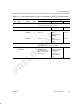
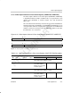
Table 3–16. Video Capture Channel x Field 1 Start Register (VCxSTRT1) Field Descriptions
Description
Bit field
†
symval
†
Value BT.656 or Y/C Mode Raw Data Mode TSI Mode
31–28 Reserved – 0 Reserved. The reserved bit location is always read as 0. A
value written to this field has no effect.
27–16 VCYSTART OF(value) 0–FFFh Starting line number. Not used. Not used.
15 SSE Startup synchronization enable bit.
DISABLE 0 Not used. Startup
synchronization is
disabled.
Not used.
ENABLE 1 Not used. Startup
synchronization is
enabled.
Not used.
14–12 Reserved – 0 Reserved. The reserved bit location is always read as 0. A
value written to this field has no effect.
11–0 VCXSTART
VCVBLNKP
OF(value) 0–FFFh VCXSTART bits define
the starting pixel
number. Must be an
even number (LSB is
treated as 0).
VCVBLNKP bits
define the minimum
CAPEN inactive
time to be
interpreted as a
vertical blanking
period.
Not used.
†
For CSL implementation, use the notation VP_VCxSTRT1_field_symval