
Interpolated Control (VIC) Port Reference Guide

Video Capture Registers
3-57Video Capture PortSPRU629
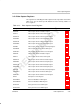
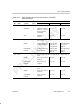
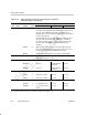
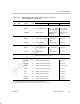
Table 3–15. Video Capture Channel A Control Register (VCACTL)
Field Descriptions (Continued)
Description
Bit TSI ModeRaw Data ModeBT.656 or Y/C ModeValuesymval
†
field
†
6 FRAME
‡
Capture frame (data) bit.
NONE 0 Do not capture frame. Do not capture
single data block.
Do not capture
single packet.
FRMCAP 1 Capture frame. Capture single
data block.
Capture single
packet.
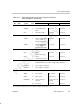
5 CF2
‡
Capture field 2 bit.
NONE 0 Do not capture field 2. Do not capture
field 2.
Not used.
FLDCAP 1 Capture field 2. Capture field 2. Not used.
4 CF1
‡
Capture field 1 bit.
NONE 0 Do not capture field 1. Do not capture
field 1.
Not used.
FLDCAP 1 Capture field 1. Capture field 1. Not used.
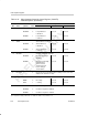
3 Reserved – 0 Reserved. The reserved bit location is always read as 0. A value
written to this field has no effect.
2–0 CMODE Capture mode select bit.
BT656B 0 Enables 8-bit BT.656 mode. Not used.
BT656D 1h Enables 10-bit BT.656 mode. Not used.
RAWB 2h Enables 8-bit raw data mode. 8-bit TSI mode.
RAWD 3h Enables 10-bit raw data mode. Not used.
YCB 4h Enables 16-bit Y/C mode. Not used.
YCD 5h Enables 20-bit Y/C mode. Not used.
RAW16 6h Enables 16-bit raw mode. Not used.
RAW20 7h Enables 20-bit raw mode. Not used.
†
For CSL implementation, use the notation VP_VCACTL_field_symval
‡
For complete encoding of these bits, see Table 3–6, Table 3–11, and Table 3–12.