
Interpolated Control (VIC) Port Reference Guide

Video Capture Registers
3-55Video Capture PortSPRU629
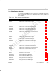
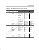
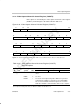
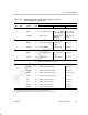
Table 3–15. Video Capture Channel A Control Register (VCACTL)
Field Descriptions (Continued)
Description
Bit TSI ModeRaw Data ModeBT.656 or Y/C ModeValuesymval
†
field
†
18 FLDD Field detect method bit. (Channel A only)
EAVFID 0 1
st
line EAV or FID
input.
Not used. Not used.
FDL 1 Field detect logic. Not used. Not used.
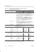
17 VRST VCOUNT reset method bit.
V1EAV 0 Start of vertical blank
(1
st
V = 1 EAV or
VCTL2 active edge)
Not used.
Not used.
V0EAV 1 End of vertical blank
(1
st
V = 0 EAV or
VCTL2 inactive edge)
Not used.
Not used.
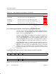
16 HRST HCOUNT reset method bit.
EAV 0 EAV or
VCTL1 active edge.
Not used. Not used.
SAV 1 SAV or
VCTL1 inactive edge.
Not used. Not used.
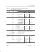
15 VCEN Video capture enable bit. Other bits in VCACTL (except RSTCH
and BLKCAP bits) may only be changed when VCEN = 0.
DISABLE 0 Video capture is disabled.
ENABLE 1 Video capture is enabled.
14–13
PK10B 10-bit packing format select bit.
ZERO 0 Zero extend Zero extend Not used.
SIGN 1h Sign extend Sign extend Not used.
DENSEPK 2h Dense pack (zero
extend)
Dense pack (zero
extend)
Not used.
– 3h Reserved Reserved Not used.
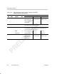
†
For CSL implementation, use the notation VP_VCACTL_field_symval
‡
For complete encoding of these bits, see Table 3–6, Table 3–11, and Table 3–12.