
Interpolated Control (VIC) Port Reference Guide

Video Capture Registers
Video Capture Port3-50 SPRU629
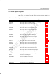
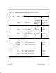
Table 3–13. Video Capture Control Registers (Continued)
Acronym SectionRegister Name
TSISTCMPL TSI System Time Clock Compare LSB Register 3.13.16
TSISTCMPM TSI System Time Clock Compare MSB Register 3.13.17
TSISTMSKL TSI System Time Clock Compare Mask LSB Register 3.13.18
TSISTMSKM TSI System Time Clock Compare Mask MSB Register 3.13.19
TSITICKS
TSI System Time Clock Ticks Interrupt Register 3.13.20
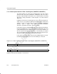
3.13.1 Video Capture Channel x Status Register (VCASTAT, VCBSTAT)
The video capture channel x status register (VCASTAT, VCBSTAT) indicates
the current status of the video capture channel. The VCxSTAT is shown in
Figure 3–29 and described in Table 3–14.
In BT.656 capture mode, the VCXPOS and VCYPOS bits indicate the
HCOUNT and VCOUNT values, respectively, to track the coordinates of the
most recently received pixel. The F1C, F2C, and FRMC bits indicate comple-
tion of fields or frames and may need to be cleared by the DSP for capture to
continue, depending on the selected frame capture operation (see section 3.4.1).
In raw data and TSI modes, the VCXPOS and VCYPOS bits reflect the lower
and upper 12 bits, respectively, of the 24-bit data counter that tracks the
number of received data samples. The FRMC bit indicates when an entire data
packet has been received and may need to be cleared by the DSP for capture
to continue, depending on the selected frame operation (see section 3.7.1 and
section 3.8.5).
Figure 3–29. Video Capture Channel x Status Register (VCASTAT, VCBSTAT)
31 30 29 28 27 16
FSYNC
FRMC F2C F1C VCYPOS
R-0 R/WC-0 R/WC-0 R/WC-0 R-0
15 13 12 11 0
Reserved VCFLD VCXPOS
R-0 R-0 R-0
Legend: R = Read only; WC = Write 1 to clear, write of 0 has no effect; -n = value after reset