
Interpolated Control (VIC) Port Reference Guide


TSI Capture Mode
3-41Video Capture PortSPRU629
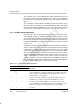
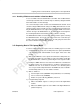
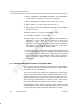
3.8.6 Writing to the FIFO
The captured TSI packet data and the associated timestamps are written into
the receive FIFO. The packet data is written first, followed by the timestamp.
The FIFO controller controls both data writes and timestamp writes into the
FIFO. The FIFO data packing is shown in Figure 3–25.
Figure 3–25. TSI FIFO Packing
TSI FIFO
TSI 2 TSI 4 TSI 6TSI 1 TSI 3 TSI 5 TSI 7
VDIN[9–2]
VCLKIN
63 5655 4847 4039 32
TSI 5 TSI 4TSI 7 TSI 6
TSI 13 TSI 12TSI 15 TSI 14
Little-Endian Packing
TSI 8 TSI 10TSI 9 TSI 11TSI 0
31 2423 1615 87 0
TSI 1 TSI 0TSI 3 TSI 2
TSI 9 TSI 8TSI 11 TSI 10
TSI FIFO
63 5655 48 47 4039 32
TSI 5TSI 4 TSI 7TSI 6
TSI 13TSI 12 TSI 15TSI 14
Big-Endian Packing
31 2423 1615 87 0
TSI 1TSI 0 TSI 3TSI 2
TSI 9TSI 8 TSI 11TSI 10
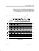
The data capture circuitry signals to the synchronizing circuit when to take a
timestamp of the hardware counters. The FIFO write controller keeps track of
number of bytes received in a packet. It multiplexes the timestamp data and
the packet data onto the FIFO write data bus. The timestamp and packet error
information are inserted after each packet in the FIFO and must use the correct
endian byte ordering. The format for the timestamp is shown in Figure 3–26
and Figure 3–27.
Figure 3–26. TSI Timestamp Format (Little Endian)
63 62 61 42 41 33 32
PERR
PSTERR Reserved PCR extension PCR
31 0
PCR