
User's Guide


CNTHI
Internal
clock
Externalclock
viaTINPL
64-bittimercounter
Timerperiod
PRDHI
Inputclock
CLKSRC
Gatedinternalclock
CP_LO
PWID_LO(CP_LO=0)
Pulsegenerator
Timerinterrupt(TINTLO)toCPU
Timerevent(TEVTLO)toEDMA controller
INVOUTP_LO
TSTAT_LObitinTCR
OutputviaTOUTL
Equalitycomparator
CNTLO
PRDLO
Timer Modes
www.ti.com
2 Timer Modes
2.1 64-Bit Timer Mode
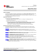
The timer can be configured as a 64-bit general-purpose (GP) timer, using the TIMMODE bits in TGCR
register. At reset, the timer is in 64-bit GP timer mode.
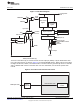
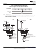
In this mode, the timer operates as a 64-bit up-counter, as shown in Figure 3. The counter registers
(CNTLO, CNTHI) and the period registers (PRDLO, PRDHI) form a 64-bit timer counter register and a
64-bit timer period register, respectively. When the timer is enabled (see Section 3.3), the timer counter
starts incrementing by 1 at every timer input clock cycle. When the timer counter matches the timer period,
it generates a maskable timer interrupt (TINTLO), a timer event (TEVTLO), and an output signal on the
timer output pin, TOUTL. When in pulse mode (CP_LO = 0), the timer output pin (TOUTL) asserts a pulse
that is 1, 2, 3, or 4 timer clock cycles wide, depending on the setting of the pulse width (PWID_LO) bits in
timer control register TCR. When the timer is configured in continuous mode, the timer counter is reset to
0 on the cycle after the timer counter reaches the timer period. The timer can be stopped, restarted, reset,
or disabled using the bits of the timer control register.
Figure 3. 64-Bit Timer Mode Block Diagram
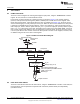
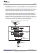
2.2 Dual 32-Bit Timer Modes
The timer can be broken down into two 32-bit timers, using the TIMMODE bits in TGCR. In this mode, the
two 32-bit timers can be operated in conjunction with each other (chained mode) or independently
(unchained mode).
8
C6472/TCI648x 64-Bit Timer SPRU818B–December 2005–Revised September 2010
Submit Documentation Feedback
Copyright © 2005–2010, Texas Instruments Incorporated