
User's Guide


Timer Registers
www.ti.com
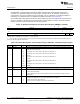
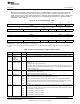
Table 12. Timer Control Register (TCR) Field Descriptions (continued)
Bit Field Value Description
19 CP_HI Clock/pulse mode bit for TIMHI. In the watchdog timer mode (TIMMODE = 10b), the pulse mode is
selected automatically and the CP_HI bit is a don’t care.
0 Pulse mode. When the timer counter reaches the timer period, the timer output appears as a pulse
with the width defined by the PWID_HI bits and the polarity defined by the INVOUTP_HI bits.
1 Clock mode. The timer output signal has a 50% duty cycle signal. When the timer counter reaches
the timer period, the level of the timer output signal is toggled (from high to low or from low to high).
18 Reserved Reserved. The reserved bit location is always read as 0. A value written to this field has no effect.
17 INVOUTP_HI Timer output inverter control bit for TIMHI.
0 The timer output is not inverted.
1 The timer output is inverted.
16 TSTAT_HI Timer status bit for TIMHI. This is a read-only bit that shows the value of the timer output.
0 Timer output is low.
1 Timer output is high.
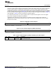
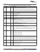
15-10 Reserved Reserved. The reserved bit location is always read as 0. A value written to this field has no effect.
9 TIEN_LO Timer input enable bit determines if the timer clock is gated by the timer input. Applicable only when
CLKSRC_LO = 0.
0 Timer clock is not gated by the timer input.
1 Timer clock is gated by a high state of the timer input synchronized with the internal clock. Timer
starts counting when timer input transitions from low to high. Timer stops counting when timer input
transitions from high to low.
8 CLKSRC_LO Clock source bit determines the clock source for the timer.
0 The clock source is the internal clock.
1 The clock source is the signal on the timer pin.
7-6 ENAMODE_ LO Enabling mode bits determine the timer mode.
00b The timer is disabled (not counting) and maintains the current value.
01b The timer is enabled one time. The timer stops after the timer counter reaches the timer period.
10b The timer is enabled continuously. The timer counter increments until it reaches the timer period.
One timer clock cycle later, the timer counter is reset to 0 and continues counting.
11b Reserved
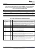
5-4 PWID_LO Pulse width bits. PWID_LO is only used in pulse mode (CP_LO = 0). PWID_LO controls the width
of the timer output signal. The polarity of the pulse is controlled by the INVOUTP_LO bit. The timer
output signal is recorded in the TSTAT_LO bit and can be made visible on the timer output pin.
00b The pulse width is 1 timer clock cycle.
01b The pulse width is 2 timer clock cycles.
10b The pulse width is 3 timer clock cycles.
11b The pulse width is 4 timer clock cycles.
3 CP_LO Clock/pulse mode bit for timer output. In the watchdog timer mode (TIMMODE = 10b), the pulse
mode is selected automatically and the CP_LO bit is a don’t care.
0 Pulse mode. When the timer counter reaches the timer period, the timer output appears as a pulse
with the width defined by the PWID_LO bits and the polarity defined by the INVOUTP_LO bits.
1 Clock mode. The timer output signal has a 50% duty cycle signal. When the timer counter reaches
the timer period, the level of the timer output signal is toggled (from high to low or from low to high).
2 INVINP_LO Timer input inverter control bit. Only affects operation if CLKSRC_LO = 1.
0 A non-inverted timer input drives the timer.
1 An inverted timer input drives the timer.
1 INVOUTP_LO Timer output inverter control bit.
0 The timer output is not inverted.
1 The timer output is inverted.
28
C6472/TCI648x 64-Bit Timer SPRU818B–December 2005–Revised September 2010
Submit Documentation Feedback
Copyright © 2005–2010, Texas Instruments Incorporated