
User's Guide


Timer Operation
www.ti.com
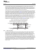
3.8 Timer Emulation Modes
The timer has an emulation management and clock speed register (EMUMGT_CLKSPD). As shown in
Table 5, the FREE and SOFT bits of EMUMGT_CLKSPD determine how the timer responds to an
emulation suspend event. An emulation suspend event corresponds to any type of emulator access to the
DSP, such as a hardware or software breakpoint, a probe point, or a printf instruction.
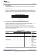
Table 5. Timer Emulation Modes Selection
FREE SOFT Emulation Mode
0 0 Default: The timer stops immediately.
0 1 The timer stops when the timer counter value increments and
reaches the value in the timer period register.
1 X The timer runs free regardless of SOFT bit status.
When using an internal clock as the timer clock source, the timer counter increments properly when single
stepping. For example, the timer increments by one for each single step if the timer clock is equal to the
CPU clock; or increments by one for every six single steps if the timer clock is equal to one-sixth of the
CPU clock.
3.9 Timer Operation Boundary Conditions
The following boundary conditions affect the timer operation.
3.9.1 Writing to and Reading From the Reserved Registers
Write the reset value to the reserved registers. Reading from the reserved registers returns zeros.
3.9.2 Timer Count = 0 and Timer Period = 0 (No Prescaler)
Consider a timer that has no prescaler:
• The 64-bit GP timer.
• TIMLO in the 32-bit dual timers configuration (unchained mode).
In the special case when timer count = 0 and timer period = 0:
• After a hardware reset and before the timer starts counting (ENAMODE bits = 00b), the timer output
signal is held low.
• Once the timer is enabled, its behavior depends on the selected enabling mode (ENAMODE bits = 01b
or 10b in the timer control register) and the selected timer output mode (CP bits = 0 or 1 in the timer
control register). The options are summarized in Table 6.
• The timer interrupt is not generated.
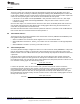
Table 6. Timer Operation When Timer Count = 0 and Timer Period = 0
Timer Operation When Timer Count = 0 and
Timer Enabling Mode Timer Output Mode Timer Period = 0 (No Prescaler)
One-time mode Pulse mode (CP bits = 0) The timer output pulses once at the first timer clock cycle, and
(ENAMODE bits = 01b) the timer stops counting at the next timer clock cycle. The pulse
width is defined by the PWID bits of the timer control register.
Clock mode (CP bits = 1) The timer output toggles once at the first timer clock cycle. The
timer stops counting at the next timer clock cycle.
Continuous mode Pulse mode (CP bits = 0) The timer output pulses once at the first timer clock cycle, and
(ENAMODE bits = 10b) the timer continues to count up. Whenever the timer counter
reaches its maximum value, it rolls around to 0 (see
Section 3.9.4), generating another pulse. The pulse width is
defined by the PWID bits of the timer control register.
Clock mode (CP bits = 1) The timer output toggles once at the first timer clock cycle and
then toggles with a frequency of half the timer clock frequency
as the timer continues to count.
16
C6472/TCI648x 64-Bit Timer SPRU818B–December 2005–Revised September 2010
Submit Documentation Feedback
Copyright © 2005–2010, Texas Instruments Incorporated