
- TMS320C645x General-Purpose Input/Output SPRU724 User's Guide

Registers
25General-Purpose Input/Output (GPIO)SPRU724
5.10 Clear Falling Edge Interrupt Register (CLR_FAL_TRIG)
The GPIO falling trigger register (FAL_TRIG) configures the edge detection
logic to trigger GPIO interrupts and EDMA events on the falling edge of GPIO
signals. Setting a bit to 1 in FAL_TRIG causes the corresponding GPIO
interrupt and EDMA event (GPINTn) to be generated on the falling edge of
GPn. FAL_TRIG is not directly accessible by the CPU; it must be configured
using the GPIO set falling trigger and clear falling trigger registers.
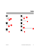
The GPIO clear falling trigger register (CLR_FAL_TRIG) is shown in Figure 11
and described in Table 11. Writing a 1 to a bit of CLR_FAL_TRIG clears the
corresponding bit in FAL_TRIG. Writing a 0 has no effect. Reading
CLR_FAL_TRIG returns the value in FAL_TRIG.
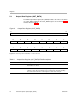
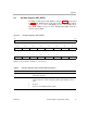
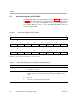
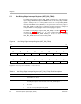
Figure 12. Clear Falling Edge Interrupt Register (CLR_FAL_TRIG)
31 16
Reserved
R-0
15 14 13 12 11 10 9 8
CLRFAL15
CLRFAL14 CLRFAL13 CLRFAL12 CLRFAL11 CLRFAL10 CLRFAL9 CLRFAL8
R/W-0 R/W-0 R/W-0 R/W-0 R/W-0 R/W-0 R/W-0 R/W-0
76543210
CLRFAL7
CLRFAL6 CLRFAL5 CLRFAL4 CLRFAL3 CLRFAL2 CLRFAL1 CLRFAL0
R/W-0 R/W-0 R/W-0 R/W-0 R/W-0 R/W-0 R/W-0 R/W-0
Legend: R = Read only; R/W = Read/Write; -n = value after reset
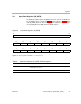
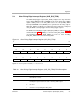
Table 12. Clear Falling Edge Interrupt Register (CLR_FAL_TRIG) Field Descriptions
Bit Field Value Description
31−16 Reserved 0 Reserved. The reserved bit location is always read as zero. A value
written to this field has no effect.
15−0 CLRFALn Writing a 1 disables falling edge detection for the corresponding GPn pin.
Reading this register returns the state of the FAL_TRIG register.
0 No effect
1 Clears the corresponding bit in FAL_TRIG