
User's Manual
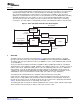
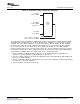

MAP
decoder
unit
A for MAP 1
and A’ for MAP2
B for MAP1
and B’ for MAP2
(only rate 1/4)
X for MAP1
or X’ for MAP2
EXT
1
: extrinsics after MAP1
EXT
2
: extrinsics after MAP2
EXT
1,2
www.ti.com
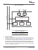
Shared-Processing (SP) Mode
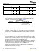
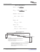
Figure 16. Shared-Processing (SP) Mode Block Diagram
The shared-processing mode allows the DSP/TCP2 system to support frames strictly larger than 20730.
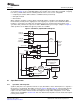
The DSP breaks the large frame into 2 or more smaller frames of 20480 or less. Each frame is called a
subframe. The size of all the subframes (except the last subframe) must be divisible by 256. The DSP
breaks the large frame into several sub-frames following the process shown below. The first subframe
does not have a header section and its tail section is equal to the prolog size. The middle subframe
header and tail section sizes are each equal to the prolog size. The last subframe header size is equal to
the prolog size and the tail section is equal to the tail size. The prolog size must be integer divisible by 8.
The sub-frames reliability portions are sequenced in order to create the full frame.
1. The first subframe (required) will have a opmode of 1. The middle subframe(s) (optional) have a
opmode of 2. The last subframe (required) will have a opmode of 3.
2. The size of all the subframes (except the last subframe) must be integer divisible by 256 and Max sub
frame size = 20480 = 80*256.
3. The first and middle subframes should have the same size. The last subframe should be approximately
the same size as the other subframes.
4. The last subframe size must be at least 129.
SPRUGK1 – March 2009 TMS320C6457 Turbo-Decoder Coprocessor 2 19
Submit Documentation Feedback