
Digital Signal Processor Product Preview

www.ti.com
PRODUCT PREVIEW
7.4.2 EDMA3 Channel Synchronization Events
TMS320C6454
Fixed-Point Digital Signal Processor
SPRS311A – APRIL 2006 – REVISED DECEMBER 2006
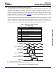
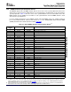
The EDMA3 supports up to 64 DMA channels that can be used to service system peripherals and to move
data between system memories. DMA channels can be triggered by synchronization events generated by
system peripherals. Table 7-3 lists the source of the synchronization event associated with each of the
DMA channels. On the C6454, the association of each synchronization event and DMA channel is fixed
and cannot be reprogrammed.
For more detailed information on the EDMA3 module and how EDMA3 events are enabled, captured,
processed, prioritized, linked, chained, and cleared, etc., see the TMS320C645x DSP Enhanced DMA
(EDMA) Controller User's Guide (literature number SPRU966 ).
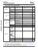
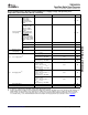
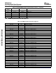
Table 7-3. C6454 EDMA3 Channel Synchronization Events
(1)
EDMA
BINARY EVENT NAME EVENT DESCRIPTION
CHANNEL
0
(2)
000 0000 DSP_EVT HPI/PCI-to-DSP event
1 000 0001 TEVTLO0 Timer 0 lower counter event
2 000 0010 TEVTHI0 Timer 0 high counter event
3 000 0011 - None
4 000 0100 - None
5 000 0101 - None
6 000 0110 - None
7 000 0111 - None
8 000 1000 - None
9 000 1001 - None
10 000 1010 - None
11 000 1011 - None
12 000 1100 XEVT0 McBSP0 transmit event
13 000 1101 REVT0 McBSP0 receive event
14 000 1110 XEVT1 McBSP1 transmit event
15 000 1111 REVT1 McBSP1 receive event
16 001 0000 TEVTLO1 Timer 1 lower counter event
17 001 0001 TEVTHI1 Timer 1 high counter event
18-43 - - None
44 010 1100 ICREVT I2C receive event
45 010 1101 ICXEVT I2C transmit event
46-47 - - None
48 011 0000 GPINT0 GPIO event 0
49 011 0001 GPINT1 GPIO event 1
50 011 0010 GPINT2 GPIO event 2
51 011 0011 GPINT3 GPIO event 3
52 011 0100 GPINT4 GPIO event 4
53 011 0101 GPINT5 GPIO event 5
54 011 0110 GPINT6 GPIO event 6
55 011 0111 GPINT7 GPIO event 7
56 011 1000 GPINT8 GPIO event 8
57 011 1001 GPINT9 GPIO event 9
(1) In addition to the events shown in this table, each of the 64 channels can also be synchronized with the transfer completion or alternate
transfer completion events. For more detailed information on EDMA event-transfer chaining, see the TMS320C645x DSP Enhanced
DMA (EDMA) Controller User's Guide (literature number SPRU966 ).
(2) HPI boot and PCI boot are terminated using a DSP interrupt. The DSP interrupt is registered in bit 0 (channel 0) of the EDMA Event
Register (ER). This event must be cleared by software before triggering transfers on DMA channel 0.
Submit Documentation Feedback C64x+ Peripheral Information and Electrical Specifications 99