
Digital Signal Processor Product Preview

www.ti.com
PRODUCT PREVIEW
TMS320C6454
Fixed-Point Digital Signal Processor
SPRS311A – APRIL 2006 – REVISED DECEMBER 2006
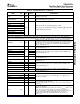
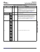
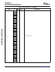
Table 2-3. Terminal Functions (continued)
SIGNAL
TYPE
(1)
IPD/IPU
(2)
DESCRIPTION
NAME NO.
This pin is the EMAC collision sense (MCDL) ( I) for MII [default] or GMII.
MCOL K3 I/O/Z
MACSEL[1:0] dependent.
This pin is either the EMAC transmit enable (MTXEN) ( O) for MII [default],
MTXEN/RMTXEN J5 I/O/Z
RMII, or GMII. MACSEL[1:0] dependent.
MTXD7 N5
MTXD6 M3
MTXD5 L5
EMAC transmit data bus for MII [default], RMII, or GMII.
MTXD4 L3
O/Z
These pins function as EMAC transmit data pins (MTXD[x:0]) ( O) for MII, RMII,
MTXD3 K4
or GMII. MACSEL[1:0] dependent.
MTXD2 M4
MTXD1/RMTXD1 L4
MTXD0/RMTXD0 M1
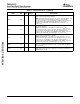
ETHERNET MAC (EMAC) [RGMII]
There are two configuration pins — the MAC_SEL[1:0] (AEA[10:9] pins) that select one of the four interface modes (MII, RMII, GMII, or
RGMII) for the EMAC/MDIO interface. For more detailed information on the EMAC configuration pins, see Section 3 , Device Configuration.
RGMII reference clock ( O). This 125-MHz reference clock is provided as a
convenience. It can be used as a clock source to a PHY, so that the PHY may
RGREFCLK C4 O/Z generate RXC clock to communicate with the EMAC. This clock is stopped
while the device is in reset. This pin is available only when RGMII mode is
selected ( MACSEL[1:0] =11).
RGMII transmit clock ( O). This pin is available only when RGMII mode is
RGTXC D4 O/Z
selected (MACSEL[1:0] =11).
RGTXD3 A2
RGTXD2 C3
RGMII transmit data [3:0] ( O). This pin is available only when RGMII mode is
O/Z
selected (MACSEL[1:0] =11).
RGTXD1 B3
RGTXD0 A3
RGMII transmit enable ( O). This pin is available only when RGMII mode is
RGTXCTL D3 O/Z
selected (MACSEL[1:0] =11).
RGMII receive clock ( I). This pin is available only when RGMII mode is selected
RGRXC E3 I
(MACSEL[1:0] =11).
RGRXD3 C1 I
RGRXD2 E4 I
RGMII receive data [3:0] ( I). This pin is available only when RGMII mode is
selected (MACSEL[1:0] =11).
RGRXD1 E2 I
RGRXD0 E1 I
RGMII receive control ( I). This pin is available only when RGMII mode is
RGRXCTL C2 I
selected (MACSEL[1:0] =11).
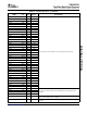
RESERVED FOR TEST
RSV02 V5
RSV03 W3
Reserved. These pins must be connected directly to core supply (CV
DD
) for
proper device operation.
RSV04 N11
RSV05 P11
RSV07 G4 I Reserved. This pin must be connected directly to 1.5-/1.8-V I/O supply
(DV
DD15
) for proper device operation.
Note: If the EMAC RGMII is not used, these pins can be connected directly to
RSV09 D26 I
ground (V
SS
) .
Reserved. This pin must be connected to ground (V
SS
) via a 200- Ω resistor for
proper device operation.
NOTE: If the DDR2 Memory Controller is not used, the V
REFSSTL
, RSV11, and
RSV12 pins can be connected directly to ground (V
SS
) to save power.
RSV11 D24
However, connecting these pins directly to ground will prevent boundary-scan
from functioning on the DDR2 Memory Controller pins. To preserve
boundary-scan functionality on the DDR2 Memory Controller pins, see
Section 7.3.4 .
Submit Documentation Feedback Device Overview 35