
Digital Signal Processor Product Preview

www.ti.com
PRODUCT PREVIEW
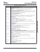
7.17.3 GPIO Electrical Data/Timing
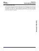
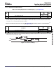
GPIx
GPOx
4
3
2
1
TMS320C6454
Fixed-Point Digital Signal Processor
SPRS311A – APRIL 2006 – REVISED DECEMBER 2006
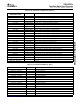
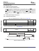
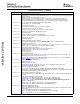
Table 7-103. Timing Requirements for GPIO Inputs
(1) (2)
(see Figure 7-74 )
-720
-850
NO. UNIT
-1000
MIN MAX
1 t
w(GPIH)
Pulse duration, GPIx high 12P ns
2 t
w(GPIL)
Pulse duration, GPIx low 12P ns
(1) P = 1/CPU clock frequency in ns. For example, when running parts at 1000 MHz, use P = 1 ns.
(2) The pulse width given is sufficient to generate a CPU interrupt or an EDMA event. However, if a user wants to have the DSP recognize
the GPIx changes through software polling of the GPIO register, the GPIx duration must be extended to at least 12P to allow the DSP
enough time to access the GPIO register through the CFGBUS.
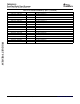
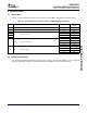
Table 7-104. Switching Characteristics Over Recommended Operating Conditions for GPIO Outputs
(1)
(see Figure 7-74 )
-720
-850
NO. PARAMETER UNIT
-1000
MIN MAX
3 t
w(GPOH)
Pulse duration, GPOx high 36P – 8
(2)
ns
4 t
w(GPOL)
Pulse duration, GPOx low 36P – 8
(2)
ns
(1) P = 1/CPU clock frequency in ns. For example, when running parts at 1000 MHz, use P = 1 ns.
(2) This parameter value should not be used as a maximum performance specification. Actual performance of back-to-back accesses of the
GPIO is dependent upon internal bus activity.
Figure 7-74. GPIO Port Timing
Submit Documentation Feedback C64x+ Peripheral Information and Electrical Specifications 215