
Digital Signal Processor Product Preview

www.ti.com
PRODUCT PREVIEW
TMS320C6454
Fixed-Point Digital Signal Processor
SPRS311A – APRIL 2006 – REVISED DECEMBER 2006
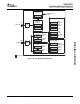
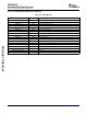
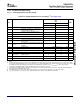
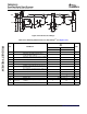
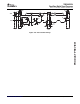
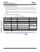
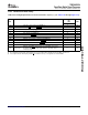
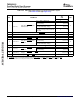
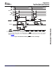
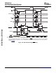
Table 7-56. Switching Characteristics for Host-Port Interface Cycles
(1) (2)
(see Table 7-56 through Figure 7-51 )
-720
-850
NO. PARAMETER UNIT
-1000
MIN MAX
Case 1. HPIC or HPIA read 5 15
Case 2. HPID read with no
9 * M + 20
auto-increment
(3)
Delay time, HSTROBE low to
Case 3. HPID read with auto-increment
1 t
d(HSTBL-HDV)
ns
9 * M + 20
DSP data valid
and read FIFO initially empty
(3)
Case 4. HPID read with auto-increment
and data previously prefetched into the 5 15
read FIFO
2 t
dis(HSTBH-HDV)
Disable time, HD high-impedance from HSTROBE high 1 4 ns
3 t
en(HSTBL-HD)
Enable time, HD driven from HSTROBE low 3 15 ns
4 t
d(HSTBL-HRDYH)
Delay time, HSTROBE low to HRDY high 12 ns
5 t
d(HSTBH-HRDYH)
Delay time, HSTROBE high to HRDY high 12 ns
Case 1. HPID read with no
10 * M + 20
auto-increment
(3)
Delay time, HSTROBE low to
6 t
d(HSTBL-HRDYL)
ns
HRDY low
Case 2. HPID read with auto-increment
10 * M + 20
and read FIFO initially empty
(3)
7 t
d(HDV-HRDYL)
Delay time, HD valid to HRDY low 0 ns
Case 1. HPIA write
(3)
5 * M + 20
Delay time, HSTROBE high to
34 t
d(DSH-HRDYL)
ns
Case 2. HPID write with no
HRDY low
5 * M + 20
auto-increment
(3)
Delay time, HSTROBE low to HRDY low for HPIA write and FIFO not
35 t
d(HSTBL-HRDYL)
40 * M + 20 ns
empty
(3)
36 t
d(HASL-HRDYH)
Delay time, HAS low to HRDY high 12 ns
(1) M = SYSCLK3 period = 6/CPU clock frequency in ns. For example, when running parts at 1000 MHz, use M = 6 ns.
(2) HSTROBE refers to the following logical operation on HCS, HDS1, and HDS2: [NOT( HDS1 XOR HDS2)] OR HCS.
(3) Assumes the HPI is accessing L2/L1 memory and no other master is accessing the same memory location.
C64x+ Peripheral Information and Electrical Specifications168 Submit Documentation Feedback