
Digital Signal Processor Product Preview

www.ti.com
PRODUCT PREVIEW
TMS320C6454
Fixed-Point Digital Signal Processor
SPRS311A – APRIL 2006 – REVISED DECEMBER 2006
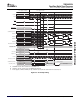
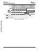
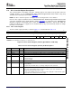
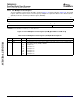
7.7.3.2 PLL Multiplier Control Register
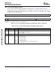
The PLL multiplier control register (PLLM) is shown in Figure 7-12 and described in Table 7-20 . The PLLM
register defines the input reference clock frequency multiplier in conjunction with the PLL divider ratio bits
(RATIO) in the PLL controller pre-divider register (PREDIV).
31 16
Reserved
R-0
15 5 4 0
Reserved PLLM
R-0 R/W-0h
LEGEND: R/W = Read/Write; R = Read only; - n = value after reset
Figure 7-12. PLL Multiplier Control Register (PLLM) [Hex Address: 029A 0110]
Table 7-20. PLL Multiplier Control Register (PLLM) Field Descriptions
Bit Field Value Description
31:5 Reserved 0 Reserved. The reserved bit location is always read as 0. A value written to this field has no effect.
4:0 PLLM PLL multiplier bits. Defines the frequency multiplier of the input reference clock in conjunction with
the PLL divider ratio bits (RATIO) in PREDIV.
0h x1 multiplier rate
Eh x15 multiplier rate
13h x20 multiplier rate
18h x25 multiplier rate
1Dh x30 multiplier rate
1Fh x32 multiplier rate
C64x+ Peripheral Information and Electrical Specifications128 Submit Documentation Feedback