
Digital Signal Processor Product Preview


www.ti.com
PRODUCT PREVIEW
7.5 Interrupts
7.5.1 Interrupt Sources and Interrupt Controller
TMS320C6454
Fixed-Point Digital Signal Processor
SPRS311A – APRIL 2006 – REVISED DECEMBER 2006
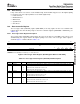
The CPU interrupts on the C6454 device are configured through the C64x+ Megamodule Interrupt
Controller. The interrupt controller allows for up to 128 system events to be programmed to any of the
twelve CPU interrupt inputs, the CPU exception input, or the advanced emulation logic. Table 8-4 shows
the mapping of system events to the interrupt controller inputs. Event numbers 0-31 correspond to the
default interrupt mapping of the device. The remaining events must be mapped using software.
For more information on the Interrupt Controller, see the TMS320C64x+ Megamodule Reference Guide
(literature number SPRU871 ).
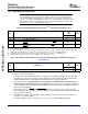
Table 7-10. C6454 DSP Interrupts
EVENT NUMBER INTERRUPT EVENT INTERRUPT SOURCE
0
(1)
EVT0 Interrupt Controller output of event combiner 0, for events 1 - 31.
1
(1)
EVT1 Interrupt Controller output of event combiner 1, for events 32 - 63.
2
(1)
EVT2 Interrupt Controller output of event combiner 2, for events 64 - 95.
3
(1)
EVT3 Interrupt Controller output of event combiner 3, for events 96 - 127.
4 - 8
(2)
Reserved Reserved. Do not use.
EMU interrupt for:
1. Host scan access
9
(2)
EMU_DTDMA
2. DTDMA transfer complete
3. AET interrupt
10
(2)
Reserved Reserved. Do not use.
11
(2)
EMU_RTDXRX EMU real-time data exchange (RTDX) receive complete
12
(2)
EMU_RTDXTX EMU RTDX transmit complete
13
(2)
IDMA0 IDMA channel 0 interrupt
14
(2)
IDMA1 IDMA channel 1 interrupt
15
(2)
DSPINT HPI/PCI-to-DSP interrupt
16 I2CINT I2C interrupt
17 MACINT Ethernet MAC interrupt
18 AEASYNCERR EMIFA error interrupt
19 - 23 Reserved Reserved. Do not use.
24 EDMA3CC_GINT EDMA3 channel global completion interrupt
25 - 39 Reserved Reserved. Do not use.
40 RINT0 McBSP0 receive interrupt
41 XINT0 McBSP0 transmit interrupt
42 RINT1 McBSP1 receive interrupt
43 XINT1 McBSP1 transmit interrupt
44 - 50 Reserved Reserved. Do not use.
51 GPINT0 GPIO interrupt
52 GPINT1 GPIO interrupt
53 GPINT2 GPIO interrupt
54 GPINT3 GPIO interrupt
55 GPINT4 GPIO interrupt
56 GPINT5 GPIO interrupt
57 GPINT6 GPIO interrupt
58 GPINT7 GPIO interrupt
(1) Interrupts 0 through 3 are non-maskable and fixed.
(2) Interrupts 4 through 15 are programmable by modifying the binary selector values in the Interrupt Selector Control registers fields.
shows the default interrupt sources for Interrupts 4 through 15.
C64x+ Peripheral Information and Electrical Specifications112 Submit Documentation Feedback