
Computer Hardware User's Guide


Reset/Interrupt/Trap Vector Map
4-17
Memory and the Instruction Cache
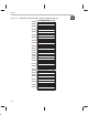
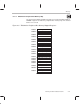
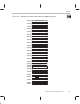
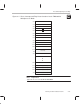
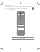
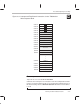
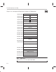
Figure 4–9. Interrupt and Trap Branch Instructions for the TMS320C31
Microcomputer Mode
809FC1h INT0
809FC2h INT1
809FC3h INT2
809FC4h INT3
809FC5h XINT0
809FC6h RINT0
809FC7h XINT1 (reserved)
809FC8h RINT1 (reserved)
809FC9h TINT0
809FCAh TINT1
809FCBh DINT
809FCCh
809FDFh
Reserved
809FE0h TRAP 0
809FE1h TRAP 1
•
•
•
809FFBh TRAP 27
809FFCh TRAP 28 (reserved)
809FFDh TRAP 29 (reserved)
809FFEh TRAP 30 (reserved)
809FFFh TRAP 31 (reserved)
Note: Traps 28–31
Traps 28–31 are reserved; do not use them.
Unlike the ’C31’s microprocessor mode, the ’C31 microcomputer/boot loader
mode uses a dual-vectoring scheme to service interrupts and trap requests. In
this dual vectoring scheme, a branch instruction rather than a vector address
is used.