
Computer Hardware User's Guide

Boot-Loader Source Code Description
C-2
C.1 Boot-Loader Source Code Description
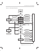
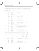
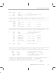
Figure C–1 shows the boot loader program flow chart. The boot loader pro-
gram starts by initializing three registers:
AR7
,
SP
, and
IR0
. These registers
hold the peripheral bus memory map register base address, the timer counter
register (used as a stack), and a flag that indicates the first block, respectively.
Then, the program checks for serial port boot load or memory boot load mode
by processing the bit fields set in the interrupt flag register (
IF
). For a serial port
boot load, the program initializes the serial port for 32-bit fixed-burst-mode
reads with an externally generated serial port clock and FSR.
For a memory boot load,
AR3
is set to the boot source address,
AR2
points
to the boot source strobe control register, and
R2
contains the value that is
stored in this strobe control register. The boot loader also sets the bit field I/
OXF0 of the I/O flag register (IOF) if the handshake mode was selected. Then
the boot loader reads the first word of the boot source program. This 32-bit
word indicates the boot memory width and the boot load program stores this
value in
R5
.
AR0
points to the
read_mc
routine that performs this read.
After reading the memory width word, the boot loader reads IOSTRB, STRB0,
and STRB1 control register values of the source program. These values are
temporarily saved in the DMA source address register, DMA destination ad-
dress register, and DMA transfer counter registers, respectively. Then, the
program reads the block size with the
read_mc
routine. If the block size is 0,
the boot loader restores the values of IOSTRB, STRB0, and STRB1 previously
saved and branches to the destination address of the first block loaded and
begins program execution. If the block size is not 0, the boot loader stores the
block size in the
BK
register. This is used as a counter in a repeat block (
RPTB
)
to transfer all the data or program in that block.
For each block, the boot loader reads the destination address and the destina-
tion strobe control word. The program stores the destination address in the
AR5
register. The destination strobe control word includes the destination
strobe identification, the contents of the destination strobe control register
(includes memory width and data size). The boot loader extracts this informa-
tion from the destination control word and stores the destination strobe-control
register memory-mapped address in the
AR4
register, the contents of the des-
tination strobe control register in the
R4
register, and the source data size in
the
R3
register. The boot loader sets the
AR1
register to the appropriate read
routine
read_s0
for serial port boot load and
read_mb
for memory boot load.
The read routine uses these registers to control the transfer of a block of data
or program.