
Computer Hardware User's Guide

Parallel XOR3 and STI
XOR3||STI
13-253
Assembly Language Instructions
Status Bits These condition flags are modified only if the destination register is R7–R0.
LUF Unaffected
LV Unaffected
UF 0
N MSB of the output
Z 1 if a 0 output is generated; 0 otherwise
V 0
C Unaffected
OVM Operation is not affected by OVM bit value.
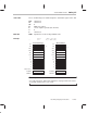
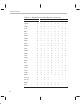
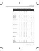
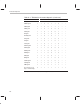
Example XOR3 *AR1++,R3,R3
|| STI R6,*–AR2(IR0)
Before Instruction After Instruction
R3 00 0000 0085 R3 00 0000 0000
R6 00 0000 00DC R6 00 0000 00DC
AR1 80 987E AR1 80 987F
AR2 80 98B4 AR2 80 98B4
IR0 8 IR0 8
LUF 0 LUF 0
LV 0 LV 0
UF 0 UF 0
N 0 N 0
Z 0 Z 0
V 0 V 0
C 0 C 0
Data memory
80987Eh 85 80987Eh 85
8098ACh 0 8098ACh 0DC
220
220
220
Note: Cycle Count
See subsection 8.5.2,
Data Loads and Stores
, on page 8-24 for the effects
of operand ordering on the cycle count.
Mode Bit