
Computer Hardware User's Guide

Test Bit Fields, 3-Operand
TSTB3
13-247
Assembly Language Instructions
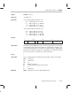
Syntax TSTB3
src2, src1
Operation
src1
AND
src2
Operands
src1
3-operand addressing modes (T):
0 0 register (R
n
1, 0 ≤
n
1 ≤ 27)
0 1 indirect (
disp
= 0, 1, IR0, IR1)
1 0 register (R
n
1, 0 ≤
n
1 ≤ 27)
1 1 indirect (
disp
= 0, 1, IR0, IR1)
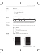
src2
3-operand addressing modes (T):
0 0 register (R
n
2, 0 ≤
n
2 ≤ 27)
0 1 register (R
n
2, 0 ≤
n
2 ≤ 127)
1 0 indirect (
disp
= 0, 1, IR0, IR1)
1 1 indirect (
disp
= 0, 1, IR0, IR1)
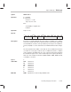
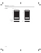
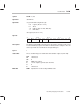
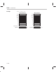
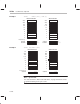
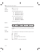
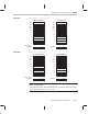
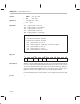
Opcode
31 24 23 16 8 7 015
001 00 1
1 11 T
src
1
00000
src
2
Description The bitwise-logical AND between the
src1
and
src2
operands is formed but is
not loaded into any register. This allows for nondestructive compares. The
src1
and
src2
operands are assumed to be unsigned integers. Although this
instruction has only two operands, it is designated as a 3-operand instruction
because operands are specified in the 3-operand format.
Cycles 1
Status Bits These condition flags are modified for all destination registers (R27–R0).
LUF Unaffected
LV Unaffected
UF 0
N MSB of the output
Z 1 if a 0 output is generated; 0 otherwise
V 0
C Unaffected
OVM Operation is not affected by OVM bit value.Mode Bit