
Computer Hardware User's Guide


TMS320C30, TMS320C31, and TMS320C32 Differences
2-27
Architectural Overview
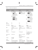
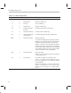
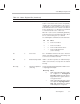
Table 2–2. Feature Set Comparison
Feature ’C30 ’C31 ’C32
External bus Two buses:
Primary bus:
32-bit data
24-bit address
STRB
active for
0h–7FFFFFh and
80A000h–FFFFFFh
Expansion bus:
32-bit data
13-bit address
MSTRB
active for
800000h–801FFFh
IOSTRB
active for
804000h–805FFFh
One bus:
32-bit data
24-bit address
STRB
active 0h–7FFFFFh
and 80A000h–FFFFFFh
One bus:
32-bit data
24-bit address
STRB0
active for
0h–7FFFFFh and
880000h–8FFFFFh;
8-, 16-, 32-bit data in
8-, 16-, 32-bit-wide
memory
STRB1
active for
900000h–FFFFFFh;
8-, 16-, 32-bit data in
8-, 16-, 32- bit-wide
memory
IOSTRB
active for
810000h–82FFFFh
ROM 4k No No
Boot loader No Yes Yes
On-chip RAM 2k
address:
809800h–809FFFh
2k
address:
809800h–809FFFh
512
address:
87FE00h–87FFFFh
DMA 1 channel
CPU greater priority than
DMA
1 channel
CPU greater priority than
DMA
2 channels
Configurable priorities
Serial ports 2 1 1
Timers 2 2 2
Interrupts Level-triggered Level-triggered Level-triggered or com-
bination of edge- and
level-triggered
Interrupt vector
table
Fixed 0–3Fh Microprocessor: 0–3Fh
fixed
Boot loader:
809C1h–809FFFh fixed
Relocatable
Package 208 PQFP
181 PGA
132 PQFP 144 PQFP
Voltage 5 V 5 V and 3.3 V 5 V
Temperature
0° to 85°C (commercial)
–40 to 125°C (extended)
–55 125°C (military)
0° to 85°C (commercial)
–40 to 125°C (extended)
–55 125°C (military)
0° to 85°C (commercial)
–40 to 125°C (extended)
–55 125°C (military)