
Computer Hardware User's Guide


LDF
Load Floating-Point Value
13-114
Syntax LDF
src, dst
Operation
src
→
dst
Operands
src
general addressing modes (G):
0 0 register (R
n
, 0 ≤
n
≤ 7)
0 1 direct
1 0 indirect (disp = 0–255, IR0, IR1)
1 1 immediate
dst
register (R
n
, 0 ≤
n
≤ 7)
Opcode
31 2423 16 8 7 015
000 00 1
1 01
dst src
G
Description The
src
operand is loaded into the
dst
register. The
dst
and
src
operands are
assumed to be floating-point numbers.
Cycles 1
Status Bits These condition flags are modified only if the destination register is R7–R0.
LUF Unaffected
LV Unaffected
UF 0
N 1 if a negative result is generated; 0 otherwise
Z 1 if a 0 result is generated; 0 otherwise
V 0
C Unaffected
OVM Operation is not affected by OVM bit value.
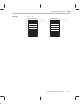
Example LDF @9800h,R2
Before Instruction After Instruction
R2 00 0000 0000 R2 01 0C52 A000
DP 080 DP 080
LUF 0 LUF 0
LV 0 LV 0
UF 0 UF 0
N 0 N 0
Z 0 Z 0
V 0 V 0
C 0 C 0
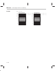
Data memory
809800 010C52A0 809800 010C52A0
2.19254303e+00
2.19254303e+00
2.19254303e+00
Mode Bit