
Computer Hardware User's Guide


IDLE2
Low-Power Idle
13-110
Syntax IDLE2 (supported by: ’LC31, ’C32, ’C30 silicon revision 7.x or
greater, ’C31 silicon revision 5.x or greater)
Operation 1 → ST(GIE)
Next PC → PC
Idle until interrupt.
Operands None
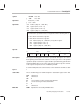
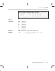
Opcode
31 2423 16 8 7 015
000 00 0
1 01
00000
00 0000000000000001
Description The IDLE2 instruction serves the same function as IDLE, except that it re-
moves the functional clock input from the internal device. This allows for ex-
tremely low power mode. The PC is incremented once, and the device remains
in an idle state until one of the external interrupts (INT0–3) is asserted.
In IDLE2 mode, the ’C3x devices that support this mode behave as follows:
The CPU, peripherals, and memory retain their previous states.
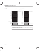
When the device is in the functional (nonemulation) mode, the clocks stop
with H1 high and H3 low.
The device remains in IDLE2 until one of the four external interrupts
(INT3
–INT0) is asserted for at least two H1 cycles. When one of the four
interrupts is asserted, the clocks start after a delay of one H1 cycle. The
clocks can start up in the phase opposite that in which they were stopped
(that is, H1 might start high when H3 was high before stopping, and H3
might start high when H1 was high before stopping). However, the H1 and
H3 clocks remain 180° out of phase with each other.
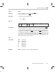
During IDLE2 operation, one of the four external interrupts must be as-
serted for at least two H2 cycles to be recognized and serviced by the
CPU. For the processor to recognize only one interrupt when it restarts op-
eration, the interrupt must be asserted for less than three cycles.
When the device is in emulation mode, the H1 and H3 clocks continue to
run normally, and the CPU operates as if an IDLE instruction had been
executed. The clocks continue to run for correct operation of the emulator.