
Computer Hardware User's Guide

STRB0_B3/A-1
HOLD
HOLDA
PRGW
R/W
D31–D0
A23–A0
DMAADDR bus
DMADATA bus
DADDR2 bus
DADDR1 bus
DDATA bus
PADDR bus
PDATA bus
Program counter/
instruction register
CPU
DMA
controller
32 24 24 32 24 24 32
32 24 32 24 24 32 24
32
Peripheral bus
Multiplexer
Multiplexer
Cache
(64 32)
RAM
block 0
(256 32)
RAM
block 1
(256 32)
Boot ROM
Enhanced
external
memory
interface
STRB0_B2/A-2
STRB0_B1
STRB0_B0
STRB1_B3/A-1
STRB1_B2/A-2
STRB1_B1
STRB1_B0
IOSTRB
Memory Organization
2-16
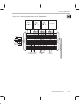
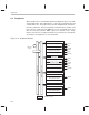
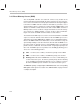
Figure 2–7. Memory Organization of the TMS320C32
A 64 32-bit instruction cache is provided to store often-repeated sections
of code, which greatly reduces the number of off-chip accesses. This allows
for code to be stored off chip in slower, lower-cost memories. The external
buses are also freed for use by the DMA, external memory fetches, or other
devices in the system.
See Chapter 4,
Memory and the Instruction Cache
, for more information.