
Computer Hardware User's Guide

ADDC
Add Integer With Carry
13-48
Syntax ADDC
src
,
dst
Operation
dst
+
src
+ C →
dst
Operands
src
general addressing modes (G):
0 0 any CPU register
0 1 direct
1 0 indirect (disp = 0–255, IR0, IR1)
1 1 immediate
dst
any CPU register
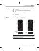
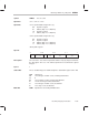
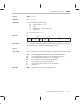
Opcode
31 2423 16 8 7 015
00000 1
src
0
dst
G0
Description The sum of the
dst
and
src
operands and the carry (C) flag is loaded into the
dst
register. The
dst
and
src
operands are assumed to be signed integers.
Cycles 1
Status Bits These condition flags are modified only if the destination register is R7–R0.
LUF Unaffected
LV 1 if an integer overflow occurs; unchanged otherwise
UF 0
N 1 if a negative result is generated; 0 otherwise
Z 1 if a 0 result is generated; 0 otherwise
V 1 if an integer overflow occurs; 0 otherwise
C 1 if a carry occurs; 0 otherwise
OVM Operation is affected by OVM bit value.
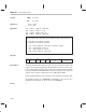
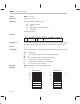
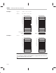
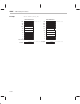
Example ADDC R1,R5
Before Instruction After Instruction
R1 00 FFFF 5C25 –41,947 R1 00 FFFF 5C25
R5 00 FFFF 019E –65,122 R5 00 FFFE 5DC4
LUF 0 LUF 0
LV 0 LV 0
UF 0 UF 0
N 0 N 0
Z 0 Z 0
V 0 V 0
C 0 C 0
–41,947
–107,068
Mode Bit