
Computer Hardware User's Guide

EXAMPLE
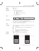
Example Instruction
13-40
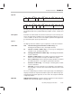
Example INST @98AEh,R5
Before Instruction After Instruction
R5 07 6690 0000 R5 00 6690 1000
R5 decimal 2.30562500e+02 R5 decimal 1.80126953e+00
DP 080 DP 080
LUF 0 LUF 0
LV 0 LV 0
UF 0 UV 0
N 0 N 0
Z 0 Z 0
V 0 V 0
C 0 C 0
Data memory
8098AEh 5CDF 8098AEh 5CDF
0200h 1234 0200h 1234
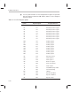
The sample code presented in the above format shows the effect of the code on
system pointers (for example, DP or SP), registers (for example, R1 or R5),
memory at specific locations, and the seven status bits. The values given for the
registers include the leading 0s to show the exponent in floating-point operations.
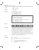
Decimal conversions are provided for all register and memory locations. The
seven status bits are listed in the order in which they appear in the assembler and
simulator (see Section 13.5 on page 13-28 and Table 13–12 on page 13-30 for
further information on these seven status bits).