
Computer Hardware User's Guide
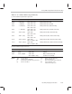
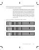

Group Addressing Mode Instruction Encoding
13-26
address, bits 15–8 the
src
3 address, and bits 7–0 the
src
4 address. The
notations mod
n
and mod
m
indicate which modification field goes with which
AR
n
or AR
m
(auxiliary register) field, respectively. The following list describes
the parallel addressing operands:
src
1 = R
n
0 ≤
n
≤ 7 (extended-precision registers R0–R7)
src
2 = R
n
0 ≤
n
≤ 7 (extended-precision registers R0–R7)
d1
If 0,
dst
1 is R0. If 1,
dst
1 is R1.
d2
If 0,
dst
2 is R2. If 1,
dst
2 is R3.
P0 ≤ P ≤ 3
src
3 indirect (
disp
= 0, 1, IR0, IR1)
src
4 indirect (
disp
= 0, 1, IR0, IR1)
As in the 3-operand addressing mode, indirect addressing in the parallel
addressing mode allows for displacements of 0 or 1 and the use of the index
registers (IR0 and IR1). The displacement of 1 is implied and is not explicitly
coded in the instruction word.
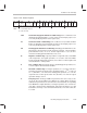
In the encoding shown for this mode in Figure 13–3, if the
src
3 and
src
4 fields
use the same auxiliary register, both addresses are correctly generated, but
only the value created by the
src
3 field is saved in the auxiliary register specified.
The assembler issues a warning if you specify this condition.
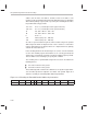
The encoding of these parallel addressing modes has been extended in the
following devices:
’C31 silicon revision 6.0 or greater
’C32 silicon revision 2.0 or greater
These addressing mode extensions also allow the use of any CPU register when-
ever an indirect operand is required in
src3
and/or
src4
operand. Figure 13–4
shows the encoding for extended parallel addressing instructions.
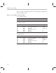
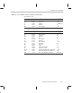
Figure 13–4. Encoding for Extended Parallel Addressing Instructions
31 30 29 28 26 25 24 23 22 21 19 18 16 15 13 12 8 9 5 40
1 0 operation P d1 d2
src
1
src
2 111
src
3 111
src
4