
Computer Hardware User's Guide
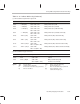
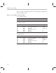

Group Addressing Mode Instruction Encoding
13-25
Assembly Language Instructions
The following values of AR
n
and AR
m
are valid:
AR
n
,0 ≤
n
≤ 7
AR
m
,0 ≤
m
≤ 7
The notation
modm
or
modn
indicates the modification field that goes with the
AR
m
or AR
n
field, respectively. Refer to Table 13–10 on page 13-22 for further
information.
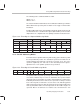
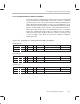
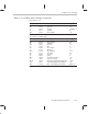
In indirect addressing of the 3-operand addressing mode, displacements (if used)
are allowed to be 0 or 1, and the index registers (IR0 and IR1) can be used. The
displacement of 1 is implied and is not explicitly coded in the instruction word.
Figure 13–2. Encoding for 3-Operand Addressing Modes
T Destination
src
1
src
2
31 28 27 23 22 21 20 16 15 13 12 11 10 8 7 5 4 3 2 0
001 operation 0 0
dst
000
src
1 000
src
2
001 operation 0 1
dst
mod
n
AR
n
000
src
2
001 operation 1 0
dst
000
src
1 mod
n
AR
n
001 operation 1 1
dst
mod
n
AR
n
mod
m
AR
m
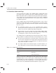
13.4.3 Parallel Addressing Modes
Instructions that use parallel addressing, indicated by || (two vertical bars), allow
the most parallelism possible. The destination operands are indicated as d1
and d2, signifying
dst
1 and
dst
2, respectively (see Figure 13–3). The source
operands, signified by
src
1 and
src
2, use the extended-precision registers.
Operation
refers to the parallel operation to be performed.
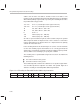
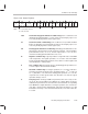
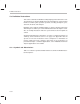
Figure 13–3. Encoding for Parallel Addressing Modes
31 30 29 26 25 24 23 22 21 19 18 16 15 11 10 8 7 3 2 0
1 0 operation P d1 d2
src
1
src
2 mod
n
AR
n
mod
m
AR
m
The parallel addressing mode (P) field specifies how the operands are to be
used, that is, whether they are source or destination. The specific relation-
ship between the P field and the operands is detailed in the description of the
individual parallel instructions. However, the operands are always encoded
in the same way. Bits 31 and 30 are set to the value of 10, indicating parallel
addressing mode instructions. Bits 25 and 24 specify the parallel addressing
mode (P) field, which defines how to interpret bits 21–0 for addressing the
src
operands. Bits 21–19 define the
src
1 address, bits 18–16 define the
src
2