
Computer Hardware User's Guide
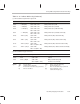

Group Addressing Mode Instruction Encoding
13-24
13.4.2 3-Operand Addressing Modes
Instructions that use the 3-operand addressing modes, such as ADDI3, LSH3,
CMPF3, or XOR3, usually have this form:
src
1 operation
src
2 →
dst
where the destination operand is signified by
dst
and the source operands by
src
1 and
src
2;
operation
defines an operation to be performed.
Note:
The
3
can be omitted from a 3-operand instruction mnemonic.
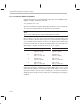
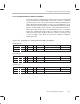
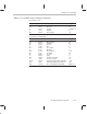
Bits 31–29 are set to the value of 001, indicating 3-operand addressing
mode instructions. Bits 22 and 21 specify the 3-operand addressing mode
(T) field, which defines how bits 15–0 are to be interpreted for addressing
the SRC operands. Bits 15–8 define the SRC1 address; bits 7–0 define the
SRC2 address. Options for bits 22 and 21 (T) are as follows:
T
src
1 addressing modes
src
2 addressing modes
00 Register mode
(any CPU register)
Register mode
(any CPU register)
0 1 Indirect mode
(
disp
= 0, 1, IR0, IR1)
Register mode
(any CPU register)
1 0 Register mode
(any CPU register)
Indirect mode
(
disp
= 0, 1, IR0, IR1)
11
Indirect mode
(
disp
= 0, 1, IR0, IR1)
Indirect mode
(
disp
= 0, 1, IR0, IR1)
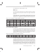
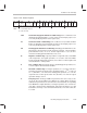
Figure 13–2 shows the encoding for 3-operand addressing. If the
src
1 and
src
2 fields both modify the same auxiliary register, both addresses are correctly
generated. However, only the value created by the
src
1 field is saved in the
auxiliary register specified. The assembler issues a warning if you specify this
condition.