
Computer Hardware User's Guide
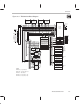
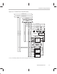

CPU Primary Register File
2-10
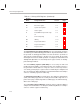
Table 2–1. Primary CPU Registers (Continued)
PageSectionAssigned Function
Register
Name
IR1 Index register 1 3.1.4 3-4
BK Block-size register 3.1.5 3-4
SP
System-stack pointer 3.1.6 3-4
ST
Status register 3.1.7 3-5
IE
CPU/DMA interrupt-enable regis-
ter
3.1.8 3-9
IF
CPU interrupt flag 3.1.9 3-11
IOF
I/O flag 3.1.10 3-16
RS
Repeat start-address 3.1.11 3-17
RE
Repeat end-address 3.1.11 3-17
RC Repeat counter 3.1.11 3-17
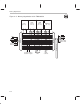
The extended-precision registers (R7–R0) can store and support operations
on 32-bit integers and 40-bit floating-point numbers. Any instruction that assumes
the operands are floating-point numbers uses bits 39–0. If the operands are
either signed or unsigned integers, only bits 31–0 are used; bits 39–32 remain
unchanged. This is true for all shift operations. See Chapter 5,
Data Formats and
Floating-Point Operation,
for extended-precision register formats for floating-
point and integer numbers.
The 32-bit auxiliary registers (AR7–AR0) are accessed by the CPU and
modified by the two ARAUs. The primary function of the auxiliary registers is
the generation of 24-bit addresses. They also can be used as loop counters
or as 32-bit general-purpose registers that are modified by the multiplier and
ALU. See Chapter 6,
Addressing Modes
, for detailed information and examples
of the use of auxiliary registers in addressing.
The data-page pointer (DP) is a 32-bit register. The eight least significant bits
(LSBs) of the data-page pointer are used by the direct addressing mode as a
pointer to the page of data being addressed. Data pages are 64K words long,
with a total of 256 pages.
The 32-bit index registers (IR0, IR1) contain the value used by the ARAU to
compute an indexed address. See Chapter 6,
Addressing Modes
, for examples
of the use of index registers in addressing.