
Computer Hardware User's Guide

DMA Controller
12-62
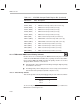
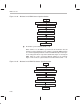
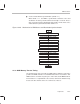
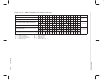
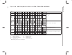
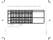
Table 12–7. CPU/DMA Interrupt-Enable Register Bits (Continued)
Abbreviation Description
Reset
Value
ETINT0 (DMA) 0 DMA timer0 interrupt enable (’C30 and ’C31)
ETINT1 (DMA) 0 DMA timer1 interrupt enable (’C30 and ’C31 only)
ETINT0 (DMA0) 0 DMA0 timer1 interrupt enable (’C32 only)
ETINT1 (DMA0) 0 DMA0 timer1 interrupt enable (’C32 only)
ETINT0 (DMA1) 0 DMA1 timer0 interrupt enable (’C32 only)
ETINT1 (DMA1) 0 DMA1 timer1 interrupt enable (’C32 only)
EDINT (DMA) 0 DMA controller interrupt enable (’C30 and ’C31)
EDINT1 (DMA0) 0 DMA0-DMA1 controller interrupt enable (’C32 only)
EDINT0 (DMA1) 0 DMA1-DMA0 controller interrupt enable (’C32 only)
EINT0 (DMA1) 0 DMA1 external interrupt 0 enable (’C32 only)
EINT1 (DMA1) 0 DMA1 external interrupt 1 enable (’C32 only)
EINT2 (DMA1) 0 DMA1 external interrupt 2 enable (’C32 only)
EINT3 (DMA1)
0 DMA1 external interrupt 2 enable (’C32 only)
12.3.5 TMS320C32 DMA Internal Priority Schemes
Because all accesses made by the two DMA channels take place over one
common internal DMA data and address bus, a priority scheme for bus arbitra-
tion is required. Within the DMA controller, two priority schemes are used to
designate which channel is serviced next:
A fixed priority scheme with channel 0 always having the highest priority
and channel 1 the lowest
A rotating priority scheme that places the most recently serviced channel
at the bottom of the priority list (default setup after reset)
12.3.5.1 Fixed Priority Scheme
This scheme provides a fixed (unchanging) priority for each channel as follows:
Priority Channel
Highest 0
Lowest 1
To select fixed priority, set the PRIORITY MODE bit (bit 14) of channel 0’s
DMA-channel control register to 1.