
Computer Hardware User's Guide

DMA Controller
12-55
Peripherals
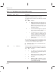
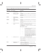
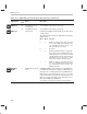
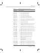
Table 12–6. DMA Global-Control Register Bits Summary (Continued)
Abbreviation
Reset
Value
Name Description
INCSRC 0 DMA source address
increment mode
If INCSRC = 1, the source address is incremented after every
read.
DECSRC 0 DMA source address
decrement mode
If DECSRC = 1, the source address is decremented after
every read.
If INCSRC = DECSRC, the source address is not modified
after a read.
INCDST 0 DMA destination
address increment
mode
If INCDST = 1, the destination address is incremented after
every write.
DECDST 0 DMA destination
address decrement
mode
If DECDST = 1, the destination address is decremented after
every write.
If INCDST = DECDST, the destination address is not modified
after a write.
SYNC 0 DMA synchronization
mode
Determines the timing synchronization between the events
initiating the source and destination transfers.
The following table summarizes the SYNC bits and DMA
synchronization.
Bit 9 Bit 8 Function
0 0 No synchronization. Enabled interrupts
are ignored (reset value).
0 1 Source synchronization. A read is per-
formed when an enabled interrupt occurs.
1 0 Destination synchronization. A write is per-
formed when an enabled interrupt occurs.
1 1 Source and destination synchronization. A
read is performed when an enabled interrupt
occurs. A write is then performed when the
next
enabled interrupt occurs.
TC 0 DMA transfer mode Affects the operation of the transfer counter.
If TC = 0, transfers are not terminated when the transfer
counter becomes 0.
If TC = 1, transfers are terminated when the transfer
counter becomes 0.
TCINT
0 DMA transfer counter
interrupt mode
If TCINT = 1, the DMA interrupt is set when the transfer
counter makes a transition to 0.
If TCINT = 0, the DMA interrupt is not set when the transfer
counter makes a transition to 0.