
Computer Hardware User's Guide

Timers
12-13
Peripherals
12.1.8 Timer Interrupts
A timer interrupt is generated whenever the TSTAT bit of the timer control register
changes from a 0 to a 1. The frequency of timer interrupts depends on whether
the timer is set up in pulse mode or clock mode.
In pulse mode, the interrupt frequency is determined by the following
equation:
=
period register
f
(timer
clock)
f
(interrupt)
f
(interrupt)
f
(timer
clock)
=
=
timer frequency
interrupt frequency
where:
In clock mode, the interrupt frequency is determined by the following
equation:
where:
f
(interrupt)
f
(timer
clock)
2 x period register
f
(timer
clock)
=
=
=
f
(interrupt)
timer frequency
interrupt frequency
The timer counter is automatically reset to 0 whenever it is equal to the value
in the timer-period register. You can use the timer interrupt for either the CPU
or the DMA. Interrupt-enable control for each timer, for either the CPU or the
DMA, is found in the CPU/DMA interrupt-enable register. Refer to Section 3.1.8,
CPU/DMA Interrupt-Enable Register (IE)
, on page 3-9 for more information.
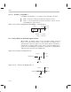
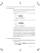
When a timer interrupt occurs, a change in the state of the corresponding
TCLK pin is observed if FUNC = 1 and CLKSRC = 1 in the timer global-control
register. The exact change in the state depends on the state of the C/P bit. In
pulse mode (C/P = 0), the width of the pulse change is 1/f (H1). In clock mode
(C/P = 1), the width of the pulse change is the period register divided by the
frequency of the timer input clock.
12.1.9 Timer Initialization/Reconfiguration
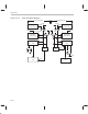
The timers are controlled through memory-mapped registers located on the
dedicated peripheral bus. The general procedure for initializing and/or recon-
figuring the timers follows:
1) Halt the timer by clearing the GO/HLD bits of the timer global-control register.
To do this, write a 0 to the timer global-control register. Note that the timers
are halted on RESET
.