
Computer Hardware User's Guide

TMS320C32 Boot Loader
11-21
Using the TMS320C31 and TMS320C32 Boot Loaders
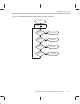
Table 11–8. Source Data Stream Structure
Word
†
Content Valid Data Entries
1 Memory width (8, 16, or 32 bits) where source program
resides
8h, 10h, or 20h, respectively
2 Value to set the IOSTRB control register at end of boot loader
process
See Section 10.7 on page 10-26
3 Value to set the STRB0 control register at end of boot loader
process
See Section 10.3.1 on page 10-7
4 Value to set the STRB1 control register at end of boot loader
process
See Section 10.6 on page 10-20
5 Size of the first data block. The block size is the number of
words in the data block (word length is specified by the data-
type size). A 0 in this entry signifies the end of the source
data stream.
0 ≤ size ≤ 2
24
6 Destination address to load the first block A valid ’C32 24-bit address
7 First block destination memory width and data-type size in
the format given in the Valid Data Entries column.
SSSSSS6
x
h
‡
8 First word of first block A ’C32 valid instruction or any 8-,
16-, or 32-bit wide data value
.
.
.
.
.
.
.
.
.
n Last word of first block A ’C32 valid instruction or any 8-,
16-, or 32-bit wide data value
.
.
.
.
.
.
.
.
.
m Size of the last data block. The block size is the number of
words in the data block (word length is specified by the
data-type size). If the next word following this block is not 0,
another block is loaded.
0 ≤ size ≤ 2
24
m + 1 Destination address to load the last block A valid ’C32
24-bit address
†
Word 1 does not exist in serial-port boot load since the source program does not reside in memory.
‡
The
SSSSSS
hexadecimal digits refer to the lower 24 bits of the strobe control register. The
x
hexadecimal digit identifies
the strobe as follows: 0 for IOSTRB
, 4 for STRB0, and 8 for STRB1. SSSSSS6xh is cleared to 0 when loading the entire field
into internal memory.