
Computer Hardware User's Guide

TMS320C32 Boot Loader
11-15
Using the TMS320C31 and TMS320C32 Boot Loaders
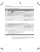
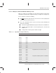
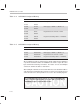
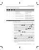
Table 11–7. Boot-Loader Mode Selection
INT0 INT1 INT2 INT3 Boot Loader Mode Source Program Location
0 1 1 1 External memory Boot 1 address 1000h
1 0 1 1 External memory Boot 2 address 810000h
1 1 0 1 External memory Boot 3 address 900000h
1 1 1 0 32-bit fixed-burst serial Serial Port
0 1 1 0 External memory with handshake Boot 1 address 1000h,
XF0 and XF1 used in handshaking
1 0 1 0 External memory with handshake Boot 2 address 810000h,
XF0 and XF1 used in handshaking
1 1 0 0 External memory with handshake Boot 3 address 900000h,
XF0 and XF1 used in handshaking
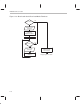
11.2.3 TMS320C32 Boot-Loading Sequence
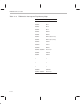
The following is the sequence of events that occur during the boot load of a
source program. Table 11–2 shows the structure of the source program.
1) Select the boot loader by resetting the ’C32 while driving the MCBL/MP
pin
high and the corresponding INT3–INT0 pins low. The MCBL/MP must stay
high during boot loading, but can be changed anytime after boot loading has
terminated. No reset is necessary when changing the INT3
–INT0 pin, as
long as the ’C32 is not accessing the overlapping memory (0h–FFFh) during
this transition. In nonhandshake mode, one of the INT3–INT0 pins can be
driven low any time after deasserting the RESET pin (driven low and then
high). While in handshake mode, two interrupt pins must be asserted before
deasserting the RESET
pin.
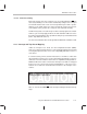
2) The status of the IF register’s INT3–INT0 bit fields dictates the boot-loading
mode. The bits are polled in the order described in the flowchart in
Figure 11–4.
3) If only the IF register’s INT3 bit field is set, the boot loader configures the
serial port for 32-bit fixed burst mode reads with an externally generated
serial-port clock and FSR. Then, it proceeds to boot load the source pro-
gram from the serial port. A header indicating the STRB0
, STRB1, and
IOSTRB control registers precedes the actual program (see Table 11–2).
These header values are loaded into the corresponding locations at the
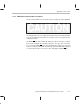
completion of the boot-load operation. The transferred data-bit order sup-
plied to the serial port must begin with the most significant bit (MSB) and
end with the least significant bit (LSB). Figure 11–5 depicts the boot-loader
serial-port flow.