
Computer Hardware User's Guide

TMS320C31 Boot Loader
11-9
Using the TMS320C31 and TMS320C32 Boot Loaders
11.1.4.1 Examples of External TMS320C31 Memory Loads
Table 11–3, Table 11–4, and Table 11–5 show memory images for byte-wide,
16-bit-wide, and 32-bit-wide configured memory (see Figure 4–2 on page 4-6).
These examples assume the following:
An INT0 signal was detected after reset was deasserted (signifying an
external memory load from boot 1).
The source program header resides at memory location 0x1000 and
defines the following:
Boot memory-type EPROMs that require two wait states and SWW = 11
A loader destination address at the beginning of the ’C31 internal
RAM block 1
A single block of memory that is 0x1FF in length
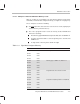
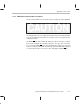
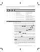
Table 11–3. Byte-Wide Configured Memory
Address Value Comments
0x1000 0x08 Memory width = 8 bits
0x1001 0x00
0x1002 0x00
0x1003 0x00
0x1004 0x58 Memory type = SWW = 11, WCNT = 2
0x1005 0x10
0x1006 0x00
0x1007 0x00
0x1008 0xFF Program block size in words = 0x1FF
0x1009 0x01
0x100A 0x00
0x100B 0x00
0x100C 0x00 Program load starting address = 0x809C00
0x100D 0x9C
0x100E 0x80
0x100F 0x00