
Computer Hardware User's Guide

32-Bit-Wide Memory Interface
10-23
TMS320C32 Enhanced External Memory Interface
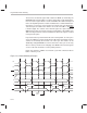
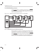
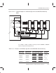
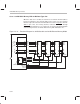
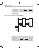
Figure 10–12. Functional Diagram for 16-Bit Data-Type Size and 32-Bit External-Memory
Width
A22
A21
A20
A19
.
.
.
A1
A0
CS
I/O(7-0)
’C32
A
23
A
22
A
21
A
20
A
19
.
.
.
A
1
A
0
D(31-24)
D(23-16)
D(15-8)
D(7-0)
1
0
Memoryinterface
A22
A21
A20
A19
.
.
.
A1
A0
CS
I/O(7-0)
A22
A21
A20
A19
.
.
.
A1
A0
CS
I/O(7-0)
A22
A21
A20
A19
.
.
.
A1
A0
CS
I/O(7-0)
STRBx_B3
STRBx_B2
STRBx_B1
STRBx_B0
A
23
A
22
A
21
A20
.
.
.
A
2
A
1
A
0
’C32’s core address bus
For example, reading or writing to memory locations 904000h to 904004h
involves the pins listed in Table 10–8.
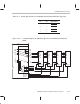
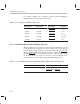
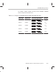
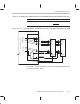
Table 10–8. Example of 16-Bit Data-Type Size and 32-Bit-Wide External Memory
Internal
Address Bus
External
Address Pins
Active Strobe Byte Enable
Accessed
Data Pins
904000h C82000h STRB1_B1 and STRB1_B0 D
15–0
904001h C82000h STRB1_B3 and STRB1_B2 D
31–16
904002h C82001h STRB1_B1 and STRB1_B0 D
15–0
904003h C82001h STRB1_B3 and STRB1_B2 D
31–16
904004h C82002h STRB1_B1 and STRB1_B0 D
15–0