
Computer Hardware User's Guide

Configuration
10-12
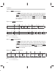
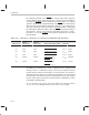
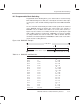
Table 10–1. STRB0, STRB1, and IOSTRB Control Register Bits (Continued)
Abbreviation DescriptionName
Reset
Value
Sign ext/
zero-fill
0 (STRB0 and STRB1
control registers only)
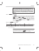
Selects the method of converting 8- and 16-bit integer data
into 32-bit integer data when transferring data from external
memory to an internal register or memory location. This field
can have the following values:
Bit 20 Physical Memory Width
0 8- or 16-bit integer reads are sign-extended to
32 bits (reset value).
1 The MSBs of 8- or 16-bit integer reads are zero-
filled to make the number 32 bits.
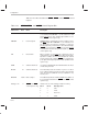
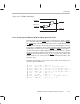
STRB config 0 STRB configuration Activates the STRB0 Bx signals when accessing data from
STRB0 or STRB1 memory spaces. This mode is useful
when accessing a single external memory bank that stores
two different data types, each mapped to a different STRB.
This field can have the following values.
Bit 21 Physical Memory Width
0 STRB0_Bx
signals are active for locations
0h–7FFFFFh and 880000h–8FFFFFh.
STRB1_Bx signals are active for locations
900000h–FFFFFFh (reset value).
1 STRB0_Bx
signals are active for locations
0h–7FFFFFh, 880000h–8FFFFFh and
900000h–FFFFFFh. STRB1_Bx
signals are
active for locations 900000h–FFFFFFh.
A functional representation of this configuration is shown in
Figure 10–7 on page 10-13.
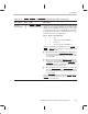
STRB switch
0 (STRB0 control regis-
ter only)
Defines whether a single cycle is inserted between back-to-
back reads when crossing STRB0 or STRB1 to STRB1 to
STRB0
boundaries (switching STRBs). The extra cycle
toggles the strobe signal during back-to-back reads. Other-
wise, the strobe remains low during back-to-back reads.
This field has the following values:
Bit 22 Physical Memory Width
0 Does not insert a single cycle between back-
to-back reads that switch from STRB0
to
STRB1
or vice-versa (reset value).
1 Inserts a single cycle between back-to-back
reads that switch from STRB0
to STRB1 or
vice-versa (reset value).